| FunWithElectronics.com |  |
| - Collection of Information for those with Electronics as a Hobby |
Up one level (Projects and circuits)
How to control an RC Servo with discrete components
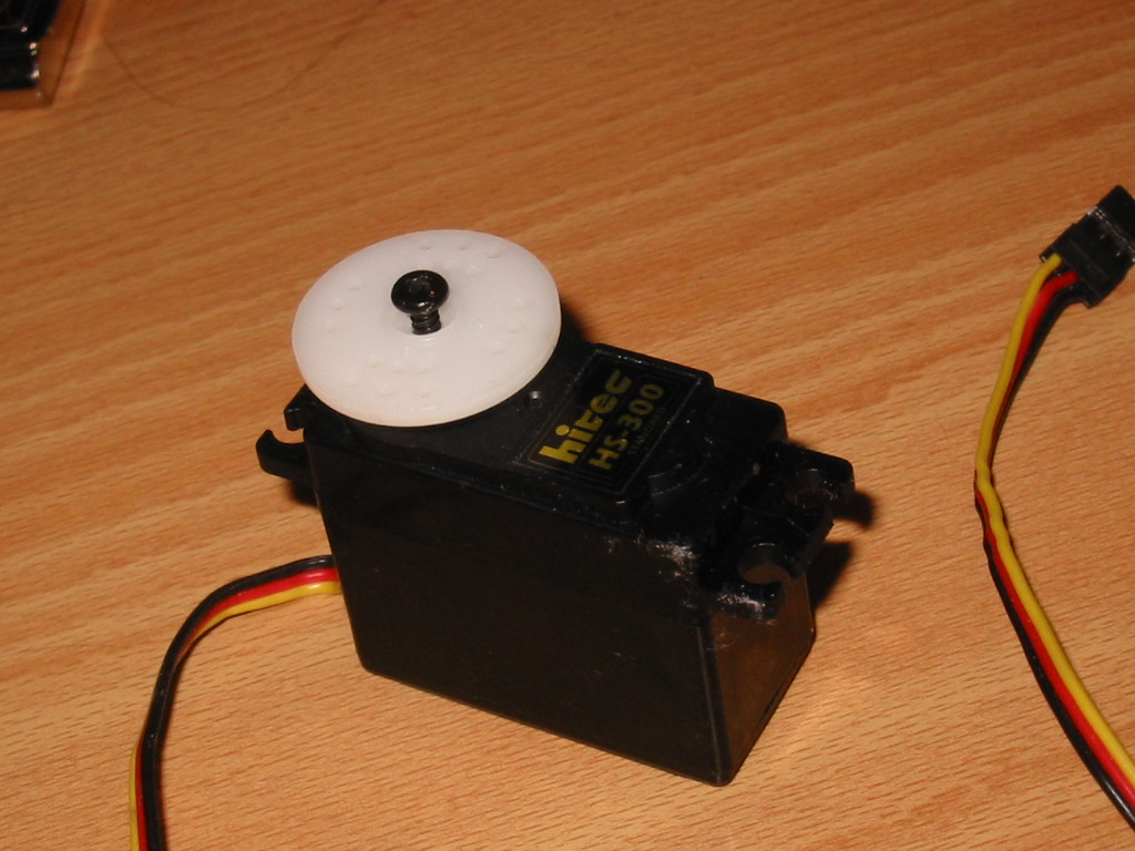 An RC servo is the kind of device you may find in a radio controlled car or in a plane. These small devices can be very useful when building things. When you first get a servo in your hands you might get curious about how you can control this. It is not very hard, but you will need some electronic circuitry. Perhaps you want to mount a small camera on top of your house and steer it from inside. The servo needs a circuit which provides it some pulses. The length of these pulses controls where the servo will point. It usually is in the order of 0.5-1.5 ms. There are actually two common ways of making these pulses. The first would be to use some timer circuitry, like a 555 timer. The second method is to use a microcontroller. If you are not familar with microcontrollers, using a 555 timer would be the easiest. On this page I also discuss making a servo controller with only discrete components. 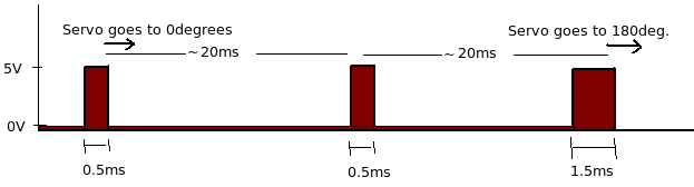
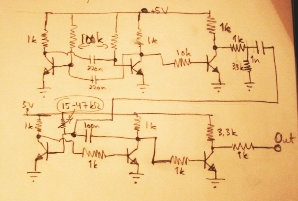
Method 1 - using discrete components (only transistors, resistors and capacitors)
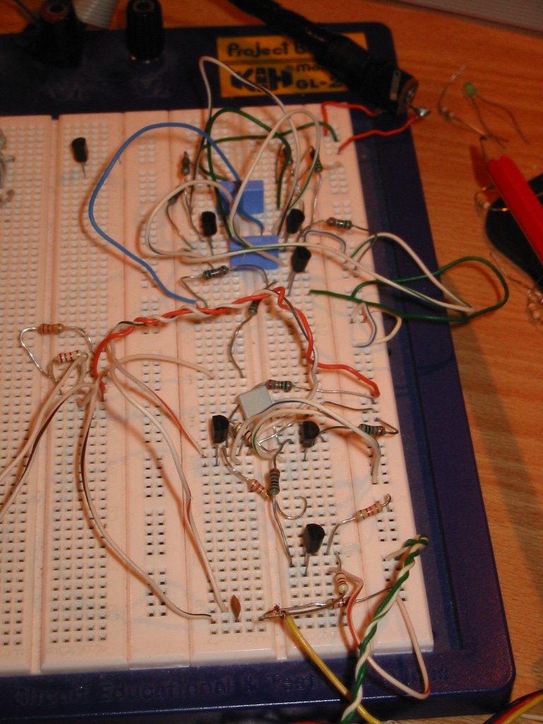
At left you can see a hand drawn schematic of the circuit I made. The circuit is the prototype I made, and there may be a lot of improvements to be made on it. At the top you can see the astable multivibrator, which generates a periodic signal with a period time of about 20ms. The bottom part is a monostable multivibrator which will output a pulse of a user controllable length every time it gets a pulse from the astable multivibrator. At right you can see the prototype put together on a breadboard. Breadboard's are fine for making projects like this. It is easy to change components and you don't have to solder anything. And if you get as far as having a good circuit, you can solder together a permanent solution on a PCB. 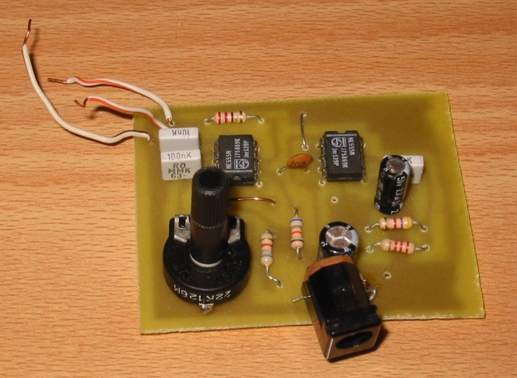 Method 2 - using 555 timer:If you think using 6 transistors and a lot of resistors and capacitors sound like too much work, you could get your hand on a couple of 555 timers. Those are IC's which you can make pulses with. We will need two of them for this to work. The first of them will control when the second will output the pulses. There should be about 20ms between each pulse. What we need then is one timer outputting a pulse every 20ms and one outputting a pulse of a variable length from 0.5 to 1.5 ms every time it gets a pulse on its input. Method 3 - using Microcontroller:If you are already familiar with microcontrollers, then it should not be very hard for you to put together a little program outputting a pulse every now and then. |
- Home
- Components
- GNU Radio and USRP
- High Voltage
- Linux
- Mathematics/physics
- Programming
- Projects and circuits
- Radio (RF)